What is your opinion on ceiling tiles in the data center?
We are building new facilities and there have been questions regarding the usefulness of a drop ceiling in the data center. Other than reducing the cost of gas fire suppression, are there other reasons a drop ceiling should be used? Assume the raised floor is 18 inches and there will be overhead cable tray and gas will be used for fire suppression. The structural height is about 14 feet.
We have multiple projects with data center with ceiling tiles, here are some comments:
1) The finish floor to ceiling height ratio needs to be taken into account, as you are correct you will severely limit your infrastructure placement.
2) The ceiling tile creates a air return plenum, just as the below the raised floor you create the air supply plenum.
3) Keep in mind the type of tile, some get damage pretty easy and release particles in the air stream.
4) By having raised floor perfs and ceiling grid return air grilles you can better distribute or control your supply and retrun air flows.
5) Ceiling Tile management is required as with raised floor tiles.
6) Cleanliness is critical.
7) I would not use fire gas suppression system in projects with ceiling tile, however I have seen a reduction on thsi approach due to cost.
Our current Datacenter has tile ceilings but it is a nightmare...we can't get our gas suppression pressure tested because the tiles leak. We have retainer clips on them but atleast one or more tiles always pop loose or the corners crack.
Besides I don't think you have tall enough ceilings to use tiles anyway. We are currently building a new datacenter and our engineers did some research and the minimum ceiling height is 14 feet. If you put in tiles you are lowering that and you won't be able to get the heat far enough away from the racks.
Good Point. We have ceiling tile in our DC and we had to install an exhaust to pump the hot air out of the space above the tile canopy. If I could do it all over again I'd nix the tile and go with open ceiling about 20-25 ft with a raised floor.
Monday, January 28, 2008
Monday, January 21, 2008
Focus on Physical Layer
The data center is the most critical resource of any business, providing the means for storage, management and dissemination of data, applications and communications. Within the data center, large amounts of information are transmitted to and from servers, switches, routers and storage equipment via the physical layer’s low-voltage cabling infrastructure. The design and deployment methods of the cabling infrastructure have a direct impact on data center space savings, proper cooling and reliability and uptime.
Space Savings
Business environments are constantly evolving, and as a result, data center requirements continuously change. Providing plenty of empty floor space when designing your data center enables the flexibility of reallocating space to a particular function, and adding new racks and equipment as needed.
As connections, bandwidth and storage requirements grow, so does the amount of data center cabling connecting key functional areas and equipment. Maximizing space resources is one of the most critical aspects of data center design. Choosing the right mix of cabling and connectivity components can have a direct impact on the amount of real estate required in your data center. Fundamentally, you cannot use the same cabling components designed for low-density LANs and expect them to perform to the level required in a data center. To properly design your data center for space savings:
• Ensure ample overhead and underfloor cable pathways for future growth.
• Select high-density patching solutions that require less rack and floor space.
• Consider higher port-density solutions like 12-fiber MPO cables and cassettes.
• Look for smaller diameter cables that take up less pathway space.
Expanding the physical space of a data center requires construction, movement of people and equipment, recabling and downtime. Expansion can cost more than the original data center build itself. Given these consequences, properly designing the data center for space savings at the start is essential. TIA-942 Telecommunications Infrastructure Standard for Data Centers, which was published in 2005 and specifies requirements and guidelines for data center infrastructures, covers cabling distances, pathways, site selection, space and layout. This standard is a valuable tool in designing your data center infrastructure for maximum space savings.
Proper Cooling
The reliability of data center equipment is directly tied to proper cooling. Servers and equipment are getting smaller and more powerful, which concentrates an enormous amount of heat into a smaller area. Proper cooling equipment is a must, as well as the use of hot aisle/cold aisle configuration where equipment racks are arranged in alternating rows of hot and cold aisles. This practice, which is recommended in the TIA-942 standard, allows cold air from the cold aisle to wash over the equipment where it is then expelled out the back into the hot aisle (see Figure 1).

Figure 1: Hot Aisle/Cold Aisle Cooling
Good cable management solutions are also necessary for proper cooling. Cables that are not properly stored and organized can block air inlets and exits, which can raise the temperature of switches and servers. Other considerations for cooling include the following:
• Increase airflow by removing obstacles to air movement, blocking unnecessary air escapes, and/or increasing the height of the raised floor.
• Spread equipment out over unused portions of the raised floor, space permitting.
• Use open racks instead of cabinets when security is not a concern, or use cabinets with mesh fronts and backs.
• Choose components that manage fiber overhead, reducing the need to store it in the raised floor and helping to increase airflow.
• Use perforated tiles with larger openings.
Reliability & Uptime
When employees and customers are unable to access the servers, storage systems and networking devices that reside in the data center, your entire organization can shut down, and millions of dollars can be lost in a matter of minutes. With 70 percent of network downtime attributed to physical layer problems, specifically cabling faults, it’s paramount that more consideration is given to the cabling infrastructure design and deployment.
As information is sent back and forth within your facility and with the outside world, huge streams of data are transferred to and from equipment areas at extremely high data rates. The low-voltage cabling deployed in the data center must consistently support the flow of data without errors that cause retransmission and delays. A substandard performing data center can be just as costly and disruptive to your business as total downtime.
Because networks expand and bandwidth demands increase, the cabling should be selected to support current needs while enabling migration to higher network speeds. In fact, the cabling chosen for the data center should be designed and implemented to outlast the applications and equipment it supports by at least 10 to 15 years. With 10 Gigabit Ethernet already a reality, that means implementing the highest-performing cable available such as augmented category 6 copper cabling and laser-optimized 50µm multimode fiber. These types of copper and fiber cabling will support bandwidth requirements for the future and ensure reliability of your data center for many years to come.
The protection of cabling and connections is a key factor in ensuring data center reliability and uptime. When cabling is bent beyond its specified minimum bend radius, it can cause transmission failures, and as more cables are added to routing paths, the possibility of bend radius violation increases (see Figure 2). The separation of cable types in horizontal pathways and physical protection of both cable and connections should also be implemented to prevent possible damage.

Figure 2: Care must be taken to avoid violating minimum
bend radius when adding fibers
Manageability is also key to maintaining uptime, and it starts with strategic, unified cable management that keeps cabling and connections properly stored and organized, easy to locate and access, and simple to reconfigure. Infrastructure components that offer proper cable management reduce the time required for identifying, routing and rerouting cables during upgrades and changes, thereby reducing downtime.
The use of a central patching location in a cross-connect scenario is the optimum solution for enhanced manageability in the data center, providing a logical and easy-to-manage infrastructure whereby all network elements have permanent equipment cable connections that once terminated, are never handled again. In this scenario, all modifications, rerouting, upgrades and maintenance activities are accomplished using semi-permanent patch cord connections on the front of the cross-connect systems (see Figure 3).

Figure 3: Interconnect vs. Cross-Connect
To improve the reliability and uptime of the data center:
• Choose the highest performing cabling and connectivity backed by a reputable manufacturer and engineered for uptime with guaranteed error-free performance.
• Select components that maintain proper bend radius, efficiently manage cable slack, and provide separation of cable types and physical protection.
• Deploy common rack frames with ample cable management that simplify cable routing and ensure paths are clearly defined and intuitive to follow.
• Use connectivity components that ensure connectors are easily defined and accessed with minimal disruption to adjacent connections.
• Deploy plug-and-play cabling solutions for faster configuration and upgrades.
• Use a central patching location in a cross-connect scenario.
Summary
The enterprise network is made up of layers with each layer supporting the one above it. When transmitting information across the network, control starts at the application layer and is moved from one layer to the next until it reaches the physical layer at the bottom where low-voltage cabling and components provide the means for sending and receiving the data. Since the total cost for low-voltage cabling components of the physical layer is but a fraction of the entire data center cost, decisions for selecting that physical layer are often taken lightly. But the fact remains that the cabling infrastructure is the core foundation upon which everything else depends – failure at the physical layer affects the entire network.
By recognizing the value of the data center cabling infrastructure, you can ensure that employees and customers have access to the servers, storage systems and networking devices they need to carry out daily business transactions and remain productive. Selecting fiber and copper cable, connectivity and cable management components that work together to satisfy space savings, reliability and uptime requirements lower the total cost of ownership. This is the ultimate means to a thriving data center and overall successful business.
About the Author
John Schmidt is the Senior Product Manager for Structured Cabling at ADC. John has been with ADC for 10 Years in a variety of design engineering and product management roles. He is the author of several articles, white papers, and presentations related to the design of telecommunications and data networks. John has a Bachelor of Science degree in Engineering from the University of Minnesota, and has 10 patents for telecommunications and network equipment design.
About ADC
Founded in 1935, ADC provides the connections for wireline, wireless, cable, broadcast and enterprise networks around the world. ADC’s network infrastructure equipment and professional services enable high-speed Internet, data, video, and voice services to residential, business, and mobile subscribers. The company sells products and services in more than 130 countries. Today, ADC is focused on serving the converged network, carrying simultaneous voice, data, and video services over wireline and wireless connections via products engineered for uptime. For more information about ADC, call 1-800-366-3891 or visit www.adc.com.
Saturday, January 19, 2008
Isolated Ground in Data Center
Do I need isolated grounds in my data center? |
| 31 Jan 2007 | Robert Macfarlane, Contributor |
| |
Why? Because it has a metal chassis with a built-in safety ground (that's code) and that chassis is screwed into a metal cabinet that had better also be grounded. You now have two ground paths: one to the standard power ground, and one to your so-called "IG." Each piece of installed equipment creates another dual-ground path, so the whole "IG" system is no longer "isolated."
"Isolated grounds" were developed for early, sensitive computers. Those computers were installed in an office environment where all sorts of other equipment were also connected, which put electrical noise on the line.
Today's boxes are much more stable, as evidenced by the fact that nearly every home has one, and power corruption problems are rarely seen. The much more sophisticated servers and storage we install in data centers does need good grounding, but that does not mean a true "isolated ground."
Dual Power Supplies
More on power supplies | ||
 | ||
| | ||
| > |
| |
| > |
| |
Data Center Grounding
Grounding -- the 'black art' | |||
|

We all know that grounding (or "earthing" as the Europeans call it) is a necessity. It's required by electrical codes; it's required by equipment manufacturers; and we all know it would be "good practice" even if it wasn't required. But exactly how to do it has probably been the subject of more debate and difference of opinion than any other aspect of the infrastructure. "Isolated grounds" are still called for by many people, even though they are actually counter-productive in the data center. And top-name manufacturers have even been known to stipulate grounding methods in their installation specifications that are just plain illegal and unbelievably dangerous. Why is it that this fundamental, and seemingly straightforward subject, is so misunderstood?
It's misunderstood because there are so many different reasons for doing it, each with its own set of concerns, considerations and installation methods. It's also misunderstood because the problems that can occur when it's done wrong are essentially invisible, difficult to comprehend, often without a good explanation and hard to track down when they happen.
Most professionals deal with only one or two types of grounding in their careers. The majority don't necessarily know that the communications industry has its own set of requirements, and don't realize that, while there are similarities, what is fine in one field doesn't always do the job in another. Let's identify some of these grounding specialties and what they're for, then pull the concepts together to get a better understanding of the principles of telecommunications grounding.
Electrical safety grounds: Probably the most fundamental of all grounds, these are required by code to protect people from injury in the event of a short or "fault" that puts current onto an equipment housing. That's why the "U-ground" pin is found on lots of appliances. One of the power wires, called the neutral (white conductor), is also grounded, but if something goes amiss with it, the "U-ground" keeps you safe. It's really bad to cut it off or to use a three-pin adapter in a two-pin socket without actually grounding the green wire or ground lug. (Appliances like power tools that just have a standard two-blade plug are "double insulated" to make sure a fault doesn't electrify the part you're holding. Because they use special construction, the manual will tell you not to disassemble it yourself.) The building power ground goes to an "earth terminal," is bonded to building steel and is also carried to every electrical panel in the building. Code requires a building safety ground to have a ground resistance of 25 Ohms or less. (It takes special equipment and techniques to measure this.) Keep this figure in mind.
Lightning grounds: These are designed to conduct lightning strikes directly to ground so they don't damage the building or its electrical systems, or injure people. Spiked rods on top of the building (called "air terminals") are the most commonly recognized form of protection, although not necessarily the best. But whatever technique is used, the intent is to carry the lightning strike to earth through the building steel or through wires run down the outside of the structure to rods driven into the ground. These ground rods are also bonded to the main electrical ground, as is the building steel. Lightning, by its nature, includes a large high frequency component. (If you studied mathematics, you will recall the Fourier Series, which defines the attributes of a sharply rising pulse, and understand why.) Therefore, it doesn't bend corners very well. All lighting wires are run with long radius bends -- no right angles. Keep this in mind as well for later in our discussion.
RF shielding and grounding: Radio frequencies are very high, (though not as complex as lightning) and therefore have very short wavelengths. Despite the experience we have daily with cell phone dead zones, RF tends to find its way into everything, especially where it is not wanted. The only way to stop RFI (radio frequency interference) is with a virtually continuous grounded shield -- often called a "brute force ground." This might be thought of as the opposite of an isolated ground. Commonly seen in broadcasting, this type of grounding is achieved by making sure all metal parts are solidly bonded together -- essentially grounded everywhere. If you have, or have ever seen, an RF shielded cabinet, you may have noticed that the doors close against hundreds of small, spring bronze fingers or against some sort of metallic braid that forms a continuous electrical connection around the entire door edge. (These cabinets are sometimes used to meet FCC regulations for RF emission from equipment and are usually labeled as such.) Keep this concept in mind as well as we proceed.
Electro-static grounds: After the mandatory electrical safety ground, this is what we want in our data centers. It's the reason we wear (or should wear) wrist straps when we work on micro-electronics and why we use anti-static floor tiles in data centers instead of carpet. Static discharge is just a personal lightning bolt. It's obviously much lower in power than nature's cloud-borne version, but it's exactly the same phenomenon -- a build-up of free electrons that suddenly finds a path to something with fewer electrons -- usually the earth, or "ground" -- and very rapidly discharges those electrons to equalize the balance. The problem is, it may find its ground path right through our sensitive and expensive hardware, where even a minute discharge, if it doesn't actually damage something, can cause data errors and even memory loss. And the smaller and faster our hardware becomes, the more vulnerable it is to static problems, either airborne or arriving as power line anomalies when our UPS is in bypass.
What we want to accomplish with an electro-static ground is not all that different from lightning protection; we want to draw those electrons away from anything important and get them to ground as quickly and as completely as we can. Recall that we said lightning, or any static discharge, is very high-frequency energy. We also said RFI, which is also high frequency, is best dealt with by grounding everything to everything. Recall also, probably from high school science, that electricity always seeks the path of least resistance. These three concepts should help us understand the requirements of the Joint TIA/EIA/ANSI Standard J-STD-607-A Commercial Building Grounding (Earthing) and Bonding Requirements for Telecommunications (ANSI/J-STD--607-A-2002)" and the concept of "equal potential grounds" that we try to achieve in a data center telecommunications environment.
If everything is well bonded to a robust and virtually omnipotent grounding system, that's the path any static discharges are going to take if the system leads back to the main building ground through a very low impedance path. This includes nearly all the stuff that might get onto your grounds from outside sources. I say "nearly all" because a sufficiently powerful lighting strike is going to go where it darn well pleases, perhaps even taking a hunk off the building in the process. As we well know, nature is more powerful than our abilities to fend her off, and once in a while she outdoes us. This is why we need good lightning protection on our building, as well as a top quality surge protector on our power system. We're now getting beyond the scope of this article, but some good information can be found here.
There are two main things we're trying to accomplish: provide a very low impedance path to ground from everything metallic in our data center; and avoid creating "circulating ground currents" in the process. Let's take these one at a time. They're really not that difficult.
Impedance is the electrical term we give to resistance when we're not dealing with direct current (DC). I'll use the proper term "impedance" in this article, but if you're more comfortable thinking of "resistance," that's fine. A low-impedance path is created in three ways: large copper conductors; short wire lengths; and clean, solid connections. The principles are simple. Longer paths require larger conductors, and good connections require the proper hardware, strongly pressure-connected to surfaces that have been well cleaned beforehand. There are many products for doing this. One of the best sources of both information and products on this subject can be found Panduit.com. There are also some excellent seminars and courses you can attend. Lyncole and MikeHolt.com.
There are two characteristics specific to the particular type of electrical energy we are dealing with, and these both go back to one concept we mentioned earlier in this article -- namely, static discharge is, by nature, a high frequency phenomenon. The two characteristics are: static energy tends to travel on the surface of the wire, rather than through it ("skin effect"); and it does not like to turn sharp corners. This is why we use stranded copper wire for most grounding and bonding connections, and why we should never make sharp bends in ground wires. They should always curve smoothly with a minimum bend radius of 8 inches. Stranded conductors provide more surface area than solid conductors for the same gauge of wire, and curves keep the energy in the wire, rather than letting it bleed off into the air or to some other metal from the corner of a sharp bend. Unfortunately, the reason for radiused bends is very difficult for most electricians to grasp, and it takes virtually constant supervision to achieve a proper installation.
Circulating ground currents create their own electrical noise, so are to be avoided. In principle, they're easy to stop. Just keep everything at the same electrical potential or voltage. Current will only flow between two points that have a difference of potential. (Recall how static discharge occurs.) If we ground everything together with heavy wires, then everything should be at "equal potential" and no current will flow. Not surprisingly, this is called an "equal potential ground" and is exactly what J-STD-607-A is trying to achieve. The difficulty is doing it in a practical way. It's unrealistic to weld everything in the building or even in just the data center, together with heavy copper bars. We need to use practical wire sizes and attach them the right way, and at the best places, to everything in the room and then run those wires the shortest reasonable distances to solid ground bars. We also need to get all of our grounding bars connected together with heavy gauge wires so they are at essentially the same potential and then get them run to the primary building ground -- the same point to which the building electrical service is connected -- so that everything stays at the same electrical level. This is where the "art" of grounding design comes in.
It should by now be obvious why "isolated grounds" have no place in the data center. The minute a metal chassis is screwed into a metal cabinet, another ground path is established -- and not a very good one either. Each piece of equipment does the same thing, until there are multiple ground paths, none of them very low-impedance, all running through small-gauge wires and ending up at the building ground via different paths of all different lengths. The result is a poor static ground and loads of circulating currents due to the many different electrical levels that result. It's a waste of money on something that will be counter-productive in the end.
We must also talk about the business of connecting to building ground. This is a safety issue, absolutely required by code. A good telecommunications ground can be built as a "separate system" all the way to the electrical vault, although it should really be bonded to building steel and local electrical panels at various places along the way. It can even have its own set of ground rods if that becomes necessary to approach the lower 5-Ohm ground resistance recommended for telecommunications services. But these ground rods had better be bonded to the main electrical ground for the building. If you have a vendor who tells you they require a "separate ground" connected only to its own ground rods, tell them to consult a qualified engineer or code authority. God forbid there should ever be something called a "ground fault" in your incoming, high-voltage, building electrical service. The soil resistance between the separated grounds will result in a huge voltage difference if a "fault" occurs, and the resulting current will instantly boil the earth. The force of the explosion could put the basement slab on the second floor, and the resulting power surge on your "separate ground" could fry everything, and everybody, that's in contact with a grounded device. In short, this is not a wise approach.
There's one more factor we will mention, but not try to explain because it's really the province of the electrical engineer to determine. This is the code requirement for a "neutral bond" on the secondary ("load") side of a transformer. The code defines a transformer, such as is often found in a large PDU and a full-time UPS, as a "separately derived source." This means that a neutral-to-ground bond is required. How this is connected to the telecommunications static ground is sometimes a little tricky and can require some analysis as well as a thorough understanding of equal potential grounds in general and the UPS and PDU designs in particular. We have often found ourselves advising the electrical engineer on this issue at the same time we provide advice regarding the telecom ground.

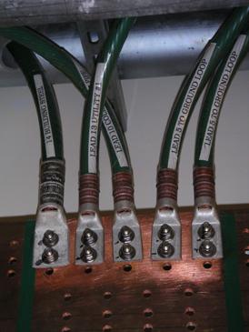
We should not close this discussion without at least mentioning the "ultimate" in telecommunications grounding practice -- the "PANI" ground. This approach actually divides the ground bar into four sectors identified as "producers," "surge arrestors," "non-isolated" and "isolated" ground networks (PANI). This is an even more exacting method of ensuring that ground currents flow within the ground bar in a way that further avoids ground current interaction. PANI grounds are used in major telecommunications carrier installations and are often required by the military. The photographs show a superb PANI ground installation. If you look closely, however, you may notice a couple of connections made after the fact by unknowledgeable electricians who must have thought that the care taken in the original installation was by someone far too anal-retentive. The electrical trades just don't understand telcom grounding.
In short, good data center grounding requires understanding, careful planning (as does any technical design), proper execution and good supervision. It is not inexpensive, but it could easily make the difference between reliably functioning equipment and never-ending data errors and failures. Take your choice.
Subscribe to:
Comments (Atom)